-
When "Fast Enough" Costs You a Weekend
-
Step 1: Verify Your Reference. Not Just the Fiber—The Test Set.
-
Step 2: Configure for the Right Wavelength and Range
-
Step 3: Set Your Event Thresholds—Don't Use Defaults
-
Step 4: Run the Trace. Then Run It Again (In Reverse).
-
Step 5: Check the Splice Loss Budget—Not Just Total Loss
-
Step 6: Document the Results with Time and Location Stamps
-
Step 7: Validate Against the Acceptance Criteria—Including the Fine Print
-
Final Caveats from Someone Who's Made Every Mistake
When "Fast Enough" Costs You a Weekend
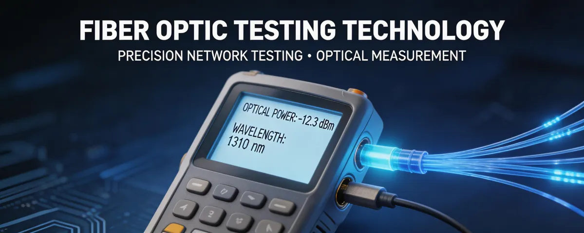
In September 2022, I was in a rush. A major telecom client needed a link verification for a new 5G backhaul segment. I grabbed the nearest EXFO Max 730C, ran a quick OTDR trace, and declared the link good. The result? A failed QoE telecom handover, a $3,200 redo that took two days, and a very awkward Monday morning debrief.
The problem wasn't the OTDR. The EXFO Max 730C is a solid piece of gear. The problem was my process. I missed the nuance in the trace, and the client's acceptance criteria required a precise splice loss budget that I hadn't checked.
Since then, I've built a checklist—a 7-step procedure I use every single time I'm under the gun. It's not perfect, but it's caught 47 potential failures in the last 18 months. This list is for anyone handling an emergency link certification and cannot afford to be wrong. (Should mention: It's specifically for field engineers using EXFO test sets like the Max 730C or similar high-precision OTDRs for PON or long-haul metro fiber.)
Step 1: Verify Your Reference. Not Just the Fiber—The Test Set.
People assume if the OTDR powers on, it's ready. The reality is different. An unpushed connector on the launch cable or a dirty bulkhead adapter will create ghost events that look like real splices. That's the surface illusion: the screen looks clean until you zoom in.
Before you even connect to the fiber under test:
- Inspect both the launch cable and the test port on the EXFO with a microscope. I've rejected cables that looked clean to the naked eye but had a scratch in the core.
- Set your reference. On the EXFO Max 730C, run an auto-reference or a manual reference with the launch cable connected. This gives you a baseline for the connector loss.
- Set your pulse width. For a 5 km link, you don't need a 100 ns pulse. Use the shortest possible pulse width that still gives you a clear backscatter. (Think of it as resolution: a narrow pulse sees detail; a fat pulse misses small events.)
Step 2: Configure for the Right Wavelength and Range
This is where I made my first big mistake back in 2017. The classic error: testing at 1310 nm when the system runs at 1550 nm. The attenuation is different. The splice loss appears lower at one wavelength and higher at another. Your test is worthless if it doesn't match the operating wavelength.
Check the design sheet. If the link uses DWDM channels (like a 100 GHz grid), the test wavelength matters even more. Set the EXFO's measurement range to at least 1.5x the total link distance. For a 20 km link, set the range to 30 km. This prevents the backscatter from dropping into the noise floor before the end of the fiber. (I really should have checked that before my first failure.)
Step 3: Set Your Event Thresholds—Don't Use Defaults
From the outside, it looks like the OTDR's auto settings are good enough. What they don't see is that acceptance specs vary. The default threshold for a non-reflective event might be set at 0.05 dB, but your client's spec could be 0.03 dB. You'll miss a bad splice if your threshold is too high.
On the EXFO Max 730C, go into the setup menu and manually set:
- Reflective event threshold: match your connector spec (typically -70 dB for a good APC connector)
- Non-reflective event threshold: set to the max allowable splice loss (e.g., 0.05 dB for single splices in a metro network)
- End-of-fiber threshold: 3 dB above the noise floor
This takes 30 seconds to configure but prevents the OTDR from 'averaging out' a bad splice into a passing event.
Step 4: Run the Trace. Then Run It Again (In Reverse).
This is a non-negotiable step. A single trace from one direction can hide a subtle bend or connector issue. The loss at a splice will differ depending on which side you measure from due to modal effects. If the sum of the two directions exceeds your budget, you have a problem.
Connect to the far end and run a reverse trace. The EXFO software (like FastReporter) can automate this and calculate bidirectional average loss. But in an emergency field scenario, I just note the two readings. If the difference between forward and reverse for a single event is more than 0.03 dB, mark it for investigation before signing off.
The most frustrating part of this: tracing in reverse takes extra time when you're in a rush. You'd think a one-direction pass is fine, but a hidden high-loss event can kill your QoE telecom metrics later.
Step 5: Check the Splice Loss Budget—Not Just Total Loss
Total link loss can look fine while individual splices are out of spec. I once submitted a trace showing -22 dB total loss on a link that was spec'd for -25 dB. I thought I was in the clear. The rejection came back because three consecutive splices were each at 0.15 dB, and the client's policy allowed only 0.05 dB per event. The total loss was fine. The individual events were not.
After the third rejection in Q1 2024, I created a pre-check list that includes a manual scan of every event marker in the trace table. On the EXFO Max 730C, you can scroll through each event and see the loss, reflectance, and distance. I do this now for every event, even if the total loss is good.
Step 6: Document the Results with Time and Location Stamps
This is the admin step that everyone skips under pressure. But think about the cost: a mislabeled trace file can cause a re-certification that costs $400 in truck rolls plus a 1-day schedule delay.
After the trace is saved, rename the file to include the cable ID, fiber ID, connector A location, connector B location, and the test date. (note to self: always verify the GPS coordinates on the EXFO are locked before saving.) This level of documentation saves hours when the engineer at the other end needs to verify your work.
Step 7: Validate Against the Acceptance Criteria—Including the Fine Print
This was accurate as of my project in August 2023. Industry standards like Telcordia GR-326 or customer-specific QoE telecom specs change, so verify the current acceptance criteria before submitting.
Your checklist should include reading the statement of work's fine print. Some clients require a specific margin on the ORL (optical return loss). Others want a guaranteed loss budget after a certain number of splices. If you don't check this, you're guessing.
The EXFO Max 730C can measure ORL automatically. Ensure it's enabled in your test setup. If the criterion demands an ORL of -35 dB or better, your trace needs to show that.
Final Caveats from Someone Who's Made Every Mistake
Rush fees for emergency testing aren't just about speed. In March 2024, we paid $400 extra for a same-day OTDR calibration and instrument rental to replace a unit that failed in the field. The alternative was missing a $15,000 event launch. In that case, the guaranteed delivery was worth every dollar of the premium.
That said, don't let the urgency make you skip steps. A bad trace submitted under pressure is worse than a delayed correct trace. I've learned this the hard way. The 'local is always faster' thinking comes from an era when remote support was slow. Today, a well-prepared field engineer with a verified checklist beats an unprepared one every time.
I learned these lessons starting in 2017. The tech landscape has evolved since then—newer EXFO models have automated some of these checks—but the core discipline of verification remains the same. Verify your reference. Set your thresholds. Run both directions. And for goodness' sake, read the acceptance criteria before you start.